
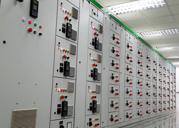
TheMotor Control Centers (MCCs) play a key role in modern electrical systems. They help control, protect, and manage multiple motors from one centralized location. If you’ve ever seen a large electrical panel in an industrial plant or commercial facility, there’s a good chance it was part of an MCC setup.
An MCC layout refers to how all electrical components are arranged inside these panels. This layout is not random. It follows a structured design that ensures safe power distribution, easy maintenance, and smooth operation. When done right, it reduces downtime and makes troubleshooting much easier.
You’ll find MCC layouts in many environments. Manufacturing plants rely on them to run machinery. Commercial buildings use them for HVAC systems. Water treatment facilities depend on them for pumps and motors. In all these cases, the goal is the same—efficient and reliable motor control.
In this guide, we’ll break down how MCC layouts work, what components they include, and how proper design improves performance and safety.
What is an MCC Layout in Electrical Systems?
An MCC layout is the physical and functional arrangement of electrical components inside a Motor Control Center. It defines how power flows, how devices connect, and how operators interact with the system. A clear layout ensures that every component works together without confusion or risk.
At its core, an MCC acts as a central hub. It distributes power to different motors and provides control over their operation. Instead of managing each motor separately, everything is handled from one organized panel.
MCC Full Form and Basic Definition
MCC stands for Motor Control Center. It is a type of electrical panel that houses multiple motor starters, control units, and protective devices in one enclosure.
Each section inside the MCC is designed to control a specific motor or group of motors. These sections often include circuit breakers, contactors, and overload relays. Together, they allow operators to start, stop, and monitor motor performance safely.
In simple terms, an MCC connects the power source to the motors while adding layers of control and protection.
Purpose of MCC Layout in Industrial Applications
The main purpose of an MCC layout is to organize and simplify motor control. Without a proper layout, systems can become hard to manage and risky to operate.
Here’s what a well-designed MCC layout helps achieve:
-
Centralized control of multiple motors
-
Reduced wiring complexity across the facility
-
Faster troubleshooting and maintenance
-
Better protection against faults and overloads
-
Improved operational efficiency
For industries that rely on continuous processes, these benefits are critical. Even a small issue can lead to downtime, so having an organized system makes a big difference.
Where MCC Layouts Are Commonly Used
MCC layouts are widely used across different sectors. Any facility that operates multiple motors can benefit from them.
Some common applications include:
-
Manufacturing plants: Control of conveyors, compressors, and production equipment
-
Commercial buildings: HVAC systems, elevators, and large ventilation units
-
Water treatment facilities: Pumps, filtration systems, and distribution motors
-
Industrial processing units: Mixing, grinding, and material handling systems

Key Components of an MCC Layout
An MCC is made up of several electrical and control components working together. Each part has a specific role. When arranged properly, they ensure smooth motor operation and system safety.
Instead of thinking of an MCC as a single panel, it helps to see it as a system of connected units. Power enters, gets distributed, and is then controlled at different levels.
Main Electrical Components Inside MCC Panels
The core components inside an MCC handle switching, protection, and control. These are the building blocks of the entire system.
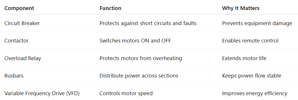
Each of these components works together. For example, when a motor starts, the contactor activates, the overload relay monitors current, and the breaker stays ready to trip if a fault occurs.
Power Distribution Components
Power distribution is the backbone of any MCC layout. It ensures that electricity reaches each motor safely and evenly.
Key elements include:
-
Busbars (Horizontal and Vertical): These are metal strips that carry large amounts of current. Horizontal busbars distribute power across sections, while vertical busbars feed individual units.
-
Incoming Feed Section: This is where the main power supply enters the MCC. It often includes a main breaker or disconnect switch.
-
Feeder Circuits: These circuits carry power from the MCC to individual motors.
-
Insulation Barriers: These separate live parts and reduce the risk of electrical faults.
A well-designed distribution system reduces voltage drops and improves overall reliability.
Control and Automation Devices
Modern MCC layouts are not just about power—they also include smart control systems. These devices help operators manage motors more efficiently.
Common control components include:
-
Programmable Logic Controllers (PLCs): Automate motor operations based on programmed logic.
-
Human Machine Interfaces (HMIs): Provide a user-friendly interface to monitor and control systems.
-
Sensors: Track temperature, pressure, and motor performance.
-
Soft Starters and VFDs: Reduce startup stress and allow speed control.
These devices improve precision. They also help reduce energy consumption and manual intervention.
Protection and Safety Devices
Safety is a top priority in any MCC layout. Protective devices prevent damage to equipment and reduce risks for operators.
Important safety components include:
-
Fuses and Circuit Breakers: Stop current flow during faults.
-
Overload Relays: Protect motors from excessive current over time.
-
Isolation Switches: Allow safe maintenance by disconnecting power.
-
Interlocks: Prevent unsafe operations, such as opening a panel while it is energized.
Together, these devices create multiple layers of protection. If one fails, another steps in to prevent serious issues.
Understanding MCC Layout Design Structure
Once you know the components, the next step is understanding how they are arranged. The layout design is what turns individual parts into a functional system. A well-structured MCC layout improves safety, simplifies maintenance, and keeps operations running smoothly.
Instead of placing components randomly, engineers follow a clear structure. This ensures proper power flow, easy access, and safe separation between sections.
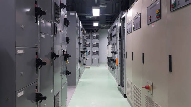
Physical Structure of MCC Panels
An MCC is usually divided into vertical sections. Each section contains multiple compartments, and each compartment controls a specific motor or load.
Key features of the physical structure include:
-
Vertical Sections: These are tall panel units placed side by side. Each section handles a group of motor controls.
-
Modular Compartments: Every compartment is designed as a separate unit. This makes it easier to install, replace, or upgrade components.
-
Plug-in or Draw-out Units: Some MCCs allow units to be removed without shutting down the entire system. This reduces downtime during maintenance.
This modular design keeps the system flexible and easy to manage over time.
Internal Layout Arrangement
Inside the panel, components are arranged in a way that separates power and control functions. This improves safety and reduces interference.
The internal layout typically includes:
-
Power Section: Handles high-current components like busbars and breakers.
-
Control Section: Contains relays, PLCs, and control wiring.
-
Segregation Barriers: Physical dividers that separate sections to prevent faults from spreading.
-
Access Zones: Designed so technicians can safely reach components for inspection or repair.
This structured arrangement minimizes risk and keeps operations organized.
Horizontal and Vertical Busbar Layout
Busbars are the main pathways for electrical current inside an MCC. Their layout plays a major role in system performance.
-
Horizontal Busbars: Run across the top or back of the panel. They distribute power to all sections.
-
Vertical Busbars: Carry power from the horizontal busbars to individual compartments.
-
Load Distribution: Ensures each motor receives the required power without imbalance.
-
Fault Management: Proper spacing and insulation help contain faults and prevent system-wide failures.
A well-planned busbar layout improves efficiency and reduces heat buildup.
Cable Routing and Wiring Layout
Cable management is often overlooked, but it has a big impact on system reliability. Poor routing can lead to confusion, overheating, or even failures.
A good wiring layout includes:
-
Defined Cable Entry Points: Cables enter from the top or bottom, depending on design needs.
-
Wireways and Cable Ducts: Keep wires organized and protected.
-
Separation of Power and Control Wiring: Reduces electrical noise and interference.
-
Clear Labeling Systems: Helps technicians quickly identify connections during maintenance.
When wiring is clean and organized, troubleshooting becomes faster and safer.
Types of MCC Layouts and Their Applications
Not all MCC layouts are the same. The design often depends on the level of control, maintenance needs, and the type of facility. Choosing the right layout can improve efficiency and reduce long-term costs.
Each type has its own advantages. Some are simple and cost-effective, while others offer flexibility and advanced control.
Fixed MCC Layout
A fixed MCC layout is the most basic design. In this setup, all components are permanently installed inside the panel. They cannot be removed without shutting down the system.
Key characteristics:
-
Simple construction
-
Lower initial cost
-
Direct wiring connections
-
Limited flexibility
Where it works best:
-
Small industrial setups
-
Facilities with minimal maintenance needs
-
Applications where downtime is manageable
While this type is budget-friendly, it can slow down repairs since the system often needs to be powered off بالكامل before any work begins.
Draw-Out MCC Layout
A draw-out MCC layout is more advanced. It allows individual units to be removed and replaced without shutting down the entire panel.
Key characteristics:
-
Removable motor control units
-
Faster maintenance and replacement
-
Improved safety during servicing
-
Reduced downtime
Where it works best:
-
Large industrial plants
-
Critical operations that run continuously
-
Facilities where downtime is costly
This layout is widely used in modern systems because it balances flexibility with safety.
Intelligent MCC Layout
An intelligent MCC layout integrates digital control and monitoring systems. It goes beyond basic motor control and adds automation features.
Key characteristics:
-
Real-time monitoring of motors
-
Integration with PLC and SCADA systems
-
Remote operation and diagnostics
-
Energy usage tracking
Where it works best:
-
Smart factories
-
Automated production lines
-
Facilities focused on energy efficiency
This type of MCC helps operators make data-driven decisions and respond quickly to system changes.
Low Voltage vs Medium Voltage MCC Layout
MCC layouts are also classified based on voltage levels. The design and application vary depending on the power requirements.
Low Voltage MCC (LV MCC):
-
Typically up to 600V
-
Used in commercial and light industrial applications
-
Easier to maintain and install
Medium Voltage MCC (MV MCC):
-
Above 600V
-
Used in heavy industries and large plants
-
Requires more advanced safety measures
Key differences:
-
MV systems handle larger loads
-
LV systems are more common and cost-effective
-
MV layouts require specialized equipment and trained personnel
MCC Layout Design Considerations
Designing an MCC layout is not just about placing components inside a panel. It requires careful planning to ensure the system runs safely, efficiently, and reliably over time. Small design mistakes can lead to costly downtime or safety risks later.
A good design balances performance, safety, and future flexibility. Below are the key factors engineers consider when planning an MCC layout.
Electrical Load and System Requirements
Every MCC layout starts with understanding the electrical load. This includes how much power the system needs and how motors will behave during operation.
Key factors to evaluate:
-
Motor ratings: Size, type, and number of motors connected to the system
-
Starting current: Motors draw higher current at startup, which must be accounted for
-
Load type: Continuous, intermittent, or variable loads
-
Diversity factor: Not all motors run at the same time, which affects total load calculation
Proper load analysis helps in selecting the right components and prevents overloading.
Environmental and Installation Factors
The environment where the MCC is installed has a direct impact on its design and lifespan. Ignoring these conditions can lead to performance issues or equipment failure.
Important considerations include:
-
Temperature: High heat can affect component performance and reduce efficiency
-
Dust and moisture: Requires proper enclosure ratings to protect internal parts
-
Corrosive environments: May need special coatings or materials
-
Indoor vs outdoor installation: Outdoor setups require weatherproof enclosures
Planning for these factors ensures long-term reliability and reduces maintenance needs.
Safety Standards and Compliance
Safety is a critical part of MCC design. Following industry standards ensures both equipment protection and operator safety.
Common standards and guidelines include:
-
NEC (National Electrical Code): Covers installation practices and safety requirements
-
NEMA standards: Define enclosure types and performance
-
UL certifications: Ensure components meet safety and quality benchmarks
Compliance is not optional. It helps prevent hazards and ensures the system meets legal requirements.
Space Optimization and Panel Arrangement
Space planning plays a big role in MCC layout design. A well-organized panel saves room while still allowing easy access.
Key design practices:
-
Compact arrangement: Efficient use of available space without overcrowding
-
Clear spacing between components: Prevents overheating and allows safe operation
-
Accessibility: Technicians should be able to reach components easily
-
Provision for expansion: Extra space for future upgrades or additional units
A layout that considers space early avoids costly redesigns later.
MCC Wiring Layout Explained
Wiring is what connects everything inside an MCC. Even if the components are high quality, poor wiring can lead to faults, confusion, and safety risks. A clean and organized wiring layout makes the system easier to operate and maintain.
In an MCC, wiring is usually divided into two main categories: power wiring and control wiring. Each has a different purpose and must be handled carefully.
Types of MCC Wiring Systems
MCC wiring is generally classified based on how circuits are grouped and protected. The most common classifications are:
-
Class 1 Wiring: Used for higher voltage control circuits. These wires carry more power and require proper insulation and spacing.
-
Class 2 Wiring: Used for low-voltage control signals. These are typically found in sensors, PLC inputs, and communication systems.
Why this matters: Separating these wiring types reduces interference and improves safety. It also helps during troubleshooting, as technicians can easily identify circuit types.
Control Wiring vs Power Wiring
Understanding the difference between control and power wiring is essential for a proper MCC layout.
Power Wiring:
-
Carries electrical energy to motors
-
Handles high current
-
Connects breakers, contactors, and motors
Control Wiring:
-
Sends signals to operate devices
-
Works at lower voltage
-
Connects switches, relays, PLCs, and sensors
Key difference: Power wiring drives the system, while control wiring tells it what to do.
Keeping these two separate prevents electrical noise and reduces the risk of system errors.
Terminal Blocks and Connections
Terminal blocks act as connection points inside the MCC. They help organize wiring and make maintenance easier.
Benefits of using terminal blocks:
-
Clear and structured connections
-
Easy identification of circuits
-
Faster installation and troubleshooting
-
Reduced risk of loose or incorrect wiring
Instead of connecting wires directly, terminal blocks create a clean interface between different sections of the system.
Best Practices for MCC Wiring
A well-planned wiring layout improves both safety and efficiency. Following best practices can prevent many common issues.
Key guidelines:
-
Use proper labeling: Every wire and terminal should be clearly marked
-
Maintain cable separation: Keep power and control wiring in separate paths
-
Use cable ducts and trays: Protect wires and keep them organized
-
Avoid overcrowding: Leave enough space to prevent overheating
-
Ensure secure connections: Loose wiring can lead to faults and failures
Good wiring practices save time during maintenance and reduce the chances of unexpected breakdowns.
How MCC Layout Works (Functionality Explained)
Understanding how an MCC works helps connect all the pieces together. Once power enters the system, it moves through a defined path. Along the way, different components control, monitor, and protect the motors.
The goal is simple. Deliver power safely, control motor operation, and respond quickly to any fault.
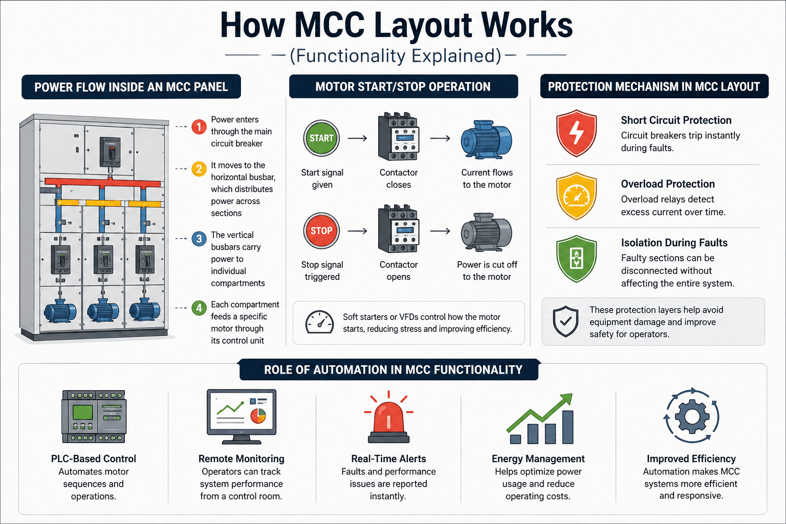
Power Flow Inside an MCC Panel
The process starts when electrical power enters the MCC through the main incoming feeder. From there, it is distributed across the panel.
Here’s how the flow typically works:
-
Power enters through the main circuit breaker
-
It moves to the horizontal busbar, which distributes power across sections
-
The vertical busbars carry power to individual compartments
-
Each compartment feeds a specific motor through its control unit
This structured flow ensures that each motor receives the correct amount of power without overloading the system.
Motor Start/Stop Operation
Motors inside an MCC do not run continuously on their own. They are controlled using devices like contactors and starters.
How it works:
-
When a start signal is given, the contactor closes
-
This allows current to flow to the motor
-
When a stop signal is triggered, the contactor opens and cuts off power
In many systems, soft starters or variable frequency drives are used to control how the motor starts. This reduces mechanical stress and improves efficiency.
Protection Mechanism in MCC Layout
Protection is built into every stage of the MCC. If something goes wrong, the system reacts quickly to prevent damage.
Common protection actions include:
-
Short circuit protection: Circuit breakers trip instantly during faults
-
Overload protection: Overload relays detect excess current over time
-
Isolation during faults: Faulty sections can be disconnected without affecting the entire system
These protection layers help avoid equipment damage and improve safety for operators.
Role of Automation in MCC Functionality
Modern MCC layouts often include automation features. These systems reduce manual work and improve control accuracy.
Key automation functions:
-
PLC-based control: Automates motor sequences and operations
-
Remote monitoring: Operators can track system performance from a control room
-
Real-time alerts: Faults and performance issues are reported तुरंत
-
Energy management: Helps optimize power usage and reduce costs
Automation makes MCC systems more efficient and responsive, especially in large facilities.
Advantages of a Well-Designed MCC Layout
A well-planned MCC layout does more than organize components. It improves performance, increases safety, and makes daily operations easier. When the design is clear and structured, the entire electrical system becomes more reliable.
In industries where downtime is costly, these advantages can have a direct impact on productivity and maintenance costs.
Centralized Control and Efficiency
One of the biggest benefits of an MCC layout is centralized control. Instead of managing motors from different locations, everything is handled from a single panel.
Key benefits:
-
Operators can start or stop multiple motors from one place
-
Control systems are easier to monitor
-
Reduced need for complex field wiring
-
Faster response to operational changes
This level of control improves efficiency, especially in large facilities with many motors running at the same time.
Improved Safety and Protection
Safety is built into every part of an MCC layout. From component selection to panel design, everything is structured to reduce risk.
How safety improves:
-
Protective devices respond quickly to faults
-
Segregated sections reduce the spread of electrical issues
-
Proper insulation lowers the risk of short circuits
-
Clear layouts reduce human error during maintenance
A safer system protects both equipment and personnel, which is critical in industrial environments.
Easy Maintenance and Troubleshooting
A clean layout makes maintenance much easier. Technicians can quickly identify components and locate issues without confusion.
Maintenance advantages:
-
Clearly labeled components and wiring
-
Modular units that can be replaced quickly
-
Reduced downtime during repairs
-
Faster fault detection
When systems are easy to maintain, they stay operational for longer periods with fewer interruptions.
Scalability and Future Expansion
A good MCC layout is designed with the future in mind. As facilities grow, new motors and equipment may need to be added.
Expansion benefits:
-
Extra space for additional units
-
Flexible design for upgrades
-
Minimal disruption when expanding the system
-
Compatibility with newer technologies
This flexibility helps businesses avoid costly redesigns and supports long-term growth.
Common MCC Layout Mistakes to Avoid
Even a well-planned system can run into problems if key details are overlooked. Many MCC issues are not due to faulty equipment but poor layout decisions. Avoiding these common mistakes can save time, reduce costs, and improve system reliability.
Poor Cable Management
Disorganized wiring is one of the most frequent issues in MCC panels. When cables are not routed properly, it becomes hard to identify connections and troubleshoot faults.
Common problems:
-
Tangled or overlapping wires
-
No clear separation between power and control cables
-
Missing or unclear labels
How to avoid it:
-
Use cable ducts and trays
-
Keep wiring paths clean and structured
-
Label all wires and terminals clearly
Good cable management improves safety and makes maintenance faster.
Overloading the System
An MCC that is not designed for the correct load can face serious issues. Overloading leads to overheating, equipment damage, and frequent tripping.
Common causes:
-
Incorrect load calculations
-
Adding new motors without system upgrades
-
Ignoring the starting current requirements
How to avoid it:
-
Perform a detailed load analysis before design
-
Leave capacity for future expansion
-
Use properly rated components
A balanced system ensures stable performance and longer equipment life.
Ignoring Safety Standards
Skipping safety guidelines can create major risks for both equipment and personnel. Standards exist to ensure systems operate safely under different conditions.
Risks involved:
-
Increased chance of electrical faults
-
Higher risk of injury during maintenance
-
Non-compliance with regulations
How to avoid it:
-
Follow NEC, NEMA, and relevant local standards
-
Use certified components
-
Include proper grounding and protection systems
Compliance is essential for safe and reliable operation.
Lack of Future Expansion Planning
Many MCC layouts are designed only for current needs. This can create problems when the system needs to grow.
Common issues:
-
No space for additional units
-
Limited capacity in busbars
-
Difficult upgrades requiring redesign
How to avoid it:
-
Plan extra space in the panel
-
Design for higher capacity where possible
-
Use modular systems for easy expansion
Planning ahead helps avoid costly modifications later.
MCC Layout vs Other Electrical Distribution Systems
MCC layouts are often compared with other electrical systems, like PCC panels and switchgear. While they may look similar, each serves a different purpose. Understanding these differences helps in choosing the right system for your project.

MCC vs PCC (Power Control Center)
The MCC and PCC panels are both used for power distribution, but their roles are different.
-
Designed specifically for controlling motors
-
Includes starters, contactors, and overload protection
-
Focuses on motor operation and control
-
Distributes power to various loads, not just motors
-
Handles incoming supply and outgoing feeders
-
Focuses on overall power management
Key difference: MCC controls motors, while PCC distributes electrical power across a facility.
MCC vs Switchgear
Switchgear is another important part of electrical systems, but it serves a different function compared to MCC.
MCC:
-
Controls and protects motors
-
Operates at low to medium voltage levels
-
Includes control and automation devices
Switchgear:
-
Protects electrical circuits from faults
-
Handles high voltage systems
-
Focuses on isolation and fault interruption
Key difference: Switchgear protects the electrical network, while MCC manages motor operations within that network.
When to Use MCC Over Other Systems
Choosing between MCC, PCC, and switchgear depends on the application.
MCC when:
-
The system involves multiple motors
-
Centralized motor control is required
-
Automation and monitoring are needed
Use PCC when:
-
Power needs to be distributed across different areas
-
The system includes mixed loads (lighting, equipment, etc.)
Use switchgear when:
-
High voltage protection is required
-
Fault isolation is critical
-
The system operates at a utility or substation level
Real-World Applications of MCC Layouts
MCC layouts are used anywhere multiple motors need reliable control. From small commercial setups to large industrial plants, they help keep operations stable and organized.
Let’s look at where they are most commonly used and why they matter in each case.
Industrial Manufacturing Plants
Manufacturing facilities depend heavily on motors. These motors run machines, conveyors, compressors, and production lines.
How MCC layouts help:
-
Central control of multiple machines
-
Smooth coordination between different processes
-
Reduced downtime during maintenance
-
Better fault isolation to prevent system-wide shutdowns
In these environments, even a short delay can affect production. A well-designed MCC layout keeps everything running efficiently.
Commercial Buildings
Large commercial buildings also rely on MCC systems, especially for mechanical operations.
Common uses include:
-
HVAC systems (heating, ventilation, and air conditioning)
-
Elevators and escalators
-
Water pumps and ventilation units
Why MCC is important here:
-
Maintains consistent indoor conditions
-
Ensures reliable building operations
-
Simplifies maintenance for facility teams
Without proper motor control, building systems can become inefficient or unreliable.
HVAC Systems
HVAC systems are one of the most common applications of MCC layouts. These systems require precise motor control to maintain airflow and temperature.
MCC benefits in HVAC:
-
Controls multiple fans and compressors
-
Allows speed adjustment using VFDs
-
Improves energy efficiency
-
Supports automated temperature control
A well-structured MCC layout helps HVAC systems operate smoothly while reducing energy costs.
Water Treatment Facilities
Water treatment plants rely on motors for pumping, filtration, and distribution.
Role of MCC layouts:
-
Control of high-capacity pumps
-
Continuous system monitoring
-
Reliable operation for critical processes
-
Quick response to faults
Since these facilities often run 24/7, reliability is essential. MCC layouts ensure uninterrupted operation and easy maintenance.
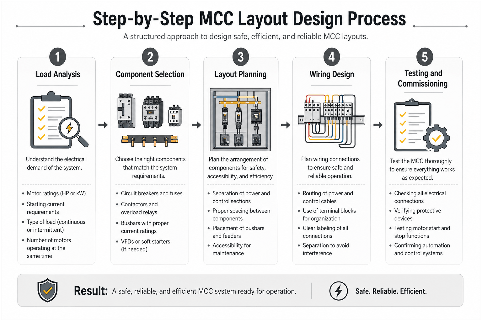
Step-by-Step MCC Layout Design Process
Designing an MCC layout requires a structured approach. Each step builds on the previous one to ensure the system is safe, efficient, and easy to maintain. Skipping any stage can lead to performance issues later.
Below is a simple breakdown of how professionals plan and implement an MCC layout.
Step 1: Load Analysis
The first step is to understand the electrical demand of the system. This includes identifying all motors and their power requirements.
What to evaluate:
-
Motor ratings (HP or kW)
-
Starting current requirements
-
Type of load (continuous or intermittent)
-
Number of motors operating at the same time
This step helps determine the overall capacity of the MCC and prevents overloading.
Step 2: Component Selection
Once the load is known, the next step is choosing the right components. Each device must match the system requirements.
Key components to select:
-
Circuit breakers and fuses
-
Contactors and overload relays
-
Busbars with proper current ratings
-
VFDs or soft starters (if needed)
Choosing the right components ensures reliability and long-term performance.
Step 3: Layout Planning
This step focuses on how components will be arranged inside the panel. A clear layout improves safety and accessibility.
Planning considerations:
-
Separation of power and control sections
-
Proper spacing between components
-
Placement of busbars and feeders
-
Accessibility for maintenance
A good layout reduces confusion and makes future work easier.
Step 4: Wiring Design
After the layout is finalized, wiring connections are planned. This step ensures all components are connected correctly and safely.
Important aspects:
-
Routing of power and control cables
-
Use of terminal blocks for organization
-
Clear labeling of all connections
-
Separation to avoid interference
Proper wiring design improves system reliability and simplifies troubleshooting.
Step 5: Testing and Commissioning
Before the MCC is put into operation, it must be tested thoroughly. This ensures everything works as expected.
Testing includes:
-
Checking all electrical connections
-
Verifying protective devices
-
Testing motor start and stop functions
-
Confirming automation and control systems
Once testing is complete, the MCC is ready for operation.
Future Trends in MCC Layout Design
MCC systems are evolving with new technology. Modern layouts are no longer limited to basic motor control. They now include smarter features that improve efficiency, monitoring, and overall system performance.
As industries move toward automation and energy optimization, MCC designs are becoming more advanced and connected.
Smart MCC Panels
Smart MCC panels are designed to provide better visibility and control over electrical systems. They use digital devices to track performance in real time.
Key features:
-
Continuous monitoring of motor conditions
-
Early detection of faults
-
Digital displays for system data
-
Integration with advanced control systems
These panels help reduce unexpected failures and improve decision-making.
IoT Integration in MCC Systems
The Internet of Things (IoT) is playing a growing role in MCC layouts. It allows systems to connect and share data across networks.
Benefits of IoT integration:
-
Remote access to system data
-
Real-time alerts and notifications
-
Predictive maintenance based on performance trends
-
Improved operational efficiency
With IoT, operators can monitor systems without being physically present at the site.
Energy-Efficient MCC Designs
Energy efficiency is becoming a priority in modern electrical systems. MCC layouts are now designed to reduce power consumption without affecting performance.
Common improvements:
-
Optimized load distribution
-
Reduced energy loss through better design
-
Monitoring of energy usage
These changes help lower operating costs and support sustainability goals.
Remote Monitoring and Control Systems
Remote control capabilities are becoming standard in many MCC setups. This allows operators to manage systems from centralized control rooms or even off-site locations.
Key advantages:
-
Faster response to system issues
-
Reduced need for on-site intervention
-
Better system oversight
-
Improved safety for personnel
Remote systems make it easier to manage large facilities with complex operations.
Conclusion
An MCC layout is more than just an arrangement of electrical components. It is a complete system designed to control, protect, and manage motors efficiently. From power distribution to automation, every part plays a role in keeping operations stable and safe.
A clear layout improves performance in several ways. It simplifies wiring, supports quick maintenance, and reduces the risk of faults. It also helps operators manage multiple motors from a single location, which saves time and effort.
As systems grow, the importance of proper design becomes even clearer. Planning for load, safety, and future expansion ensures that the MCC can handle long-term demands without frequent changes.
Whether used in industrial plants, commercial buildings, or infrastructure systems, a well-designed MCC layout provides reliability and control. It supports smooth operations while keeping both equipment and personnel protected.</p>
For businesses that depend on consistent motor performance, investing in the right MCC layout is not optional—it is essential.
Leave a Reply